





How to connect a reverse buzzer
 Jul 14, 2026|
 View:614
1. Introduction to Reverse Buzzer Connection
A reverse buzzer is an essential safety electronic device widely installed in vehicles, engineering machinery, electric carts, and industrial equipment. The core function of a reverse buzzer is to emit a continuous, high-decibel warning sound once the equipment shifts into reverse gear, effectively reminding pedestrians and surrounding staff to avoid potential collision risks. Connecting a reverse buzzer correctly is the premise of ensuring the normal operation of the reverse buzzer, while incorrect wiring will lead to the reverse buzzer failing to sound, working abnormally, or even causing circuit short circuits and equipment damage. Most standard reverse buzzers adapt to 12V or 24V DC voltage systems, matching the circuit specifications of most conventional vehicles and mechanical equipment. Mastering the standard connection method of a reverse buzzer can help users independently complete installation and maintenance, improve the safety factor of equipment reverse operation, and extend the service life of the reverse buzzer. Whether for daily vehicle refitting or industrial equipment debugging, standardized reverse buzzer connection skills are practical and necessary basic operational knowledge.
2. Step-by-Step Methods to Connect a Reverse Buzzer
Connecting a reverse buzzer follows a set of standardized, safe, and efficient operational steps, which are suitable for most common active and passive reverse buzzers on the market. Strict implementation of the following steps can ensure that the reverse buzzer is connected stably and functions perfectly in reverse standby and working states.
2.1 Prepare Tools and Confirm Reverse Buzzer Parameters
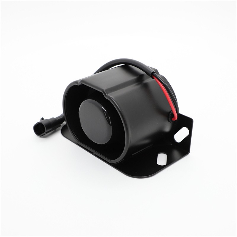
Before connecting the reverse buzzer, complete tool preparation and parameter verification to avoid wiring errors. The basic tools required include wire strippers, insulating tape, crimping terminals, a multimeter, and zip ties. First, check the rated working voltage of the reverse buzzer to match the equipment circuit voltage (12V for small vehicles, 24V for large trucks and engineering machinery). Next, confirm the wire definition of the reverse buzzer: most reverse buzzers are equipped with two core wires, including a positive power wire (usually red) and a negative grounding wire (usually black). A small number of high-end reverse buzzers have signal induction wires, which need to be confirmed according to the product manual. Only after ensuring that the reverse buzzer parameters match the equipment circuit can the subsequent formal connection be carried out.
2.2 Cut Off the Power to Ensure Circuit Safety
Power cutoff is a key prerequisite for safe reverse buzzer connection. Disconnect the battery negative terminal of the vehicle or equipment to completely cut off the power supply of the whole circuit, which can effectively prevent electric shock accidents and circuit short circuits during the reverse buzzer wiring process. After cutting off the power, use a multimeter to detect the circuit voltage to confirm no residual electricity in the circuit, creating a safe operating environment for reverse buzzer connection.
2.3 Locate the Reverse Signal Circuit
The core of connecting a reverse buzzer is to accurately find the equipment reverse signal circuit. For vehicles, the reverse signal wire is usually connected to the reverse light circuit at the tail of the car. When the equipment is in reverse gear, this wire will generate a stable voltage signal. Use a multimeter’s DC voltage gear to detect the circuit wire: hang up the reverse gear, and the wire with real-time voltage output is the reverse signal wire for connecting the reverse buzzer. Clean the surface of the circuit wire, strip off 1 to 2 centimeters of external insulating rubber to expose the copper core, preparing for subsequent docking with the reverse buzzer wire.
2.4 Complete Reverse Buzzer Wiring Docking
Start the formal wiring of the reverse buzzer. Connect the positive wire of the reverse buzzer firmly to the equipment reverse signal wire, fix the joint with crimping terminals to avoid loose virtual connection. Connect the negative wire of the reverse buzzer to the equipment grounding point, which can be the vehicle chassis metal contact or the battery negative terminal. Ensure the grounding position is clean and free of rust and oil stains to guarantee good conductivity of the reverse buzzer circuit. After the wire docking is completed, wrap all wiring joints tightly with insulating tape to prevent wire exposure and short circuit faults, ensuring the stability of the reverse buzzer circuit connection.
2.5 Fix the Reverse Buzzer and Test Operation
After the circuit connection of the reverse buzzer is completed, select a dry and ventilated position at the rear of the equipment to fix the reverse buzzer with brackets or zip ties, avoiding installation in damp and high-temperature areas to prevent damage to the reverse buzzer. Reconnect the equipment battery negative terminal, start the equipment, and hang up the reverse gear. At this time, the reverse buzzer should immediately emit a clear and continuous warning sound. If the reverse buzzer works normally, it proves that the reverse buzzer connection is successful; if the reverse buzzer does not sound, check the wiring joints and circuit conductivity again to troubleshoot faults.
3.Key Precautions for Connecting a Reverse Buzzer
Although the operation of connecting a reverse buzzer is simple, many detail precautions determine the connection safety and the long-term stable operation of the reverse buzzer. Ignoring these details will easily cause the reverse buzzer to fail, circuit failure, or even equipment damage. The core precautions for connecting a reverse buzzer are summarized as follows.
3.1 Strictly Match Reverse Buzzer Voltage Parameters
Voltage matching is the most critical point for connecting a reverse buzzer. Never connect a 12V reverse buzzer to a 24V circuit system, otherwise the reverse buzzer will be burned out instantly due to overvoltage. Similarly, a 24V reverse buzzer connected to a 12V circuit will have insufficient power and fail to make a sound. Before connecting the reverse buzzer, users must carefully check the product parameter label of the reverse buzzer and confirm the consistent voltage with the equipment circuit to ensure the reverse buzzer can work normally and avoid equipment loss.
3.2 Avoid Irregular Wiring and Poor Contact
When connecting the reverse buzzer, random wiring and disorderly wire docking are prohibited. The positive and negative wires of the reverse buzzer cannot be reversed, otherwise the internal circuit of the reverse buzzer will be shorted and damaged. In addition, the wiring joints of the reverse buzzer must be firm and reliable. Loose wiring will lead to intermittent sound of the reverse buzzer, which cannot achieve continuous warning effect. After wiring, be sure to use insulating tape and crimping parts to fix the joints to prevent wire falling off and circuit failure during equipment operation.
3.3 Pay Attention to the Installation Environment of Reverse Buzzer
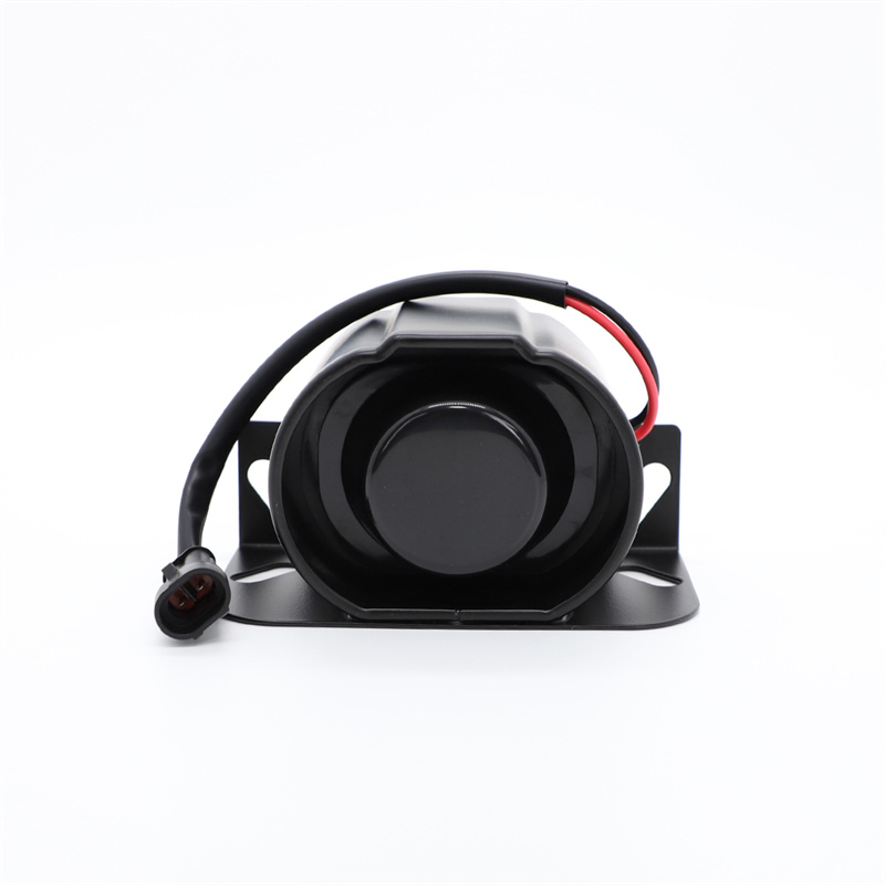
The installation position of the reverse buzzer directly affects its service life and use effect. When connecting and fixing the reverse buzzer, keep it away from water, oil, high-temperature exhaust ports and sharp mechanical friction parts. Damp environment will cause water ingress inside the reverse buzzer and damage the acoustic components; high temperature will accelerate the aging of the reverse buzzer wire and internal electronic parts. At the same time, the installation height and angle of the reverse buzzer should be reasonable to ensure the warning sound can spread outward effectively and give full play to the safety reminder function of the reverse buzzer.
3.4 Prohibit Live Operation During Connection
All operations of connecting a reverse buzzer must be carried out in a power-off state. Live wiring will not only easily cause electric shock injuries to operators but also lead to instantaneous short circuit of the reverse buzzer circuit, burning the reverse buzzer and even damaging the equipment central control circuit. After the reverse buzzer wiring is completed and all joints are inspected to be safe, the power supply can be restored for test operation, which is a necessary safety specification for reverse buzzer connection.
3.5 Regularly Inspect Reverse Buzzer Wiring Circuit
After completing the reverse buzzer connection and putting it into use, regular circuit inspection is required. Long-term vibration of equipment operation will cause loose wiring joints and aging insulating layers of the reverse buzzer. Users need to regularly check the tightness of the reverse buzzer wiring, the integrity of the insulating tape, and whether there is rust at the grounding point, so as to eliminate hidden dangers in time and ensure the long-term stable operation of the reverse buzzer.
4.Conclusion
In conclusion, connecting a reverse buzzer is a standardized and rigorous technical operation, and every step from parameter confirmation, power-off operation, circuit docking to fixed debugging directly affects the working performance and service life of the reverse buzzer. A correctly connected reverse buzzer can effectively play a safety warning role during equipment reversing, reduce the risk of pedestrian and equipment collision, and is an important guarantee for the safe operation of vehicles and mechanical equipment. In the process of connecting a reverse buzzer, users must strictly abide by operational specifications and safety precautions, adhere to voltage matching, standard wiring, and safe installation, and avoid operational errors that cause reverse buzzer failure and circuit faults. Mastering the correct connection method of a reverse buzzer and maintaining and inspecting the reverse buzzer circuit regularly can maximize the use value of the reverse buzzer, provide stable and reliable safety protection for equipment reversing operation, and ensure the safety of personnel and equipment in various working scenarios.
FAQ
Q1: What voltage does your reverse buzzer support, and what devices is it suitable for?
A: Our reverse buzzer supports universal 12V and 24V DC voltages. It fits most cars, trucks, forklifts, construction machinery and electric vehicles, meeting most industrial and vehicle reversing warning needs.
Q2: Why does the reverse buzzer fail to make sound after correct wiring?
A: Firstly check for loose or reversed wires of the reverse buzzer. Also, confirm the device reverse signal circuit works normally and no short circuit or aging wiring affects the reverse buzzer’s operation.
Q3: Is your reverse buzzer waterproof and suitable for outdoor harsh working environments?
A: Our reverse buzzer features IP65 waterproof and dustproof design. It can resist rain, dust and slight vibration, adapting to outdoor construction sites, road driving and other harsh working scenarios stably.
Q4: Will the reverse buzzer produce excessive noise damage and can its sound volume be adjusted?
A: The reverse buzzer emits standard 85-110dB warning sound, compliant with industry safety standards. The fixed volume avoids noise pollution and ensures clear warning for surrounding pedestrians and operators.
Q5: What is the service life of your reverse buzzer and how to maintain it?
A: Our reverse buzzer has a long service life of over 3 years. Regularly check wiring tightness and avoid long-term high-temperature soaking to keep the reverse buzzer in stable working condition.





View More(Total0)Comment lists